

| G series diaphragm coupling |
| ��Hits��336��AddTime��2024/7/30 8:58:50 |
Introduction
The G series diaphragm coupling provides an economical transmission solution for general equipment, using waist type diaphragms for greater torque and lower diaphragm stress.

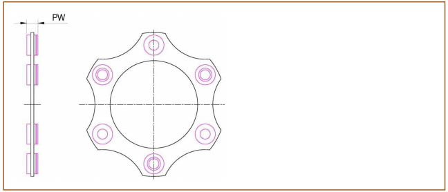
The G series diaphragm coupling has 6-hole, 8-hole, and 10 hole designs to meet different torque and compensation requirements, and has multiple structural types. It can be dynamically balanced according to requirements and can also meet API610 or API671 standards according to requirements.
• infinite life design
• overload protection
• Low additional load
• Zero maintenance, no need for lubrication and maintenance
• No gaps
performance
specifications��90-760
torque��240N.m-870000N.m
Opening diameter: to3330mm
If you need larger specifications, please consult Lanling Technology
application
• centrifugal pump
• Centrifugal compressor
• blowing machine
• refrigerator
• turbine
• other
Metal flexible component coupling
Metal flexible component couplings use metal as the flexible component for transmission
High torque, with certain axial, angular, and radial compensation
Ability, including snake shaped spring couplings and diaphragm couplings, among which snake
The type spring coupling is suitable for relatively dirty environments on site and is also driven
The moving equipment has a large impact load on the vibration meter. And membrane coupling
It is suitable for places with high speed and high requirements, such as the petrochemical industry.
Lanling Technology can provide the following types of couplings
application
The selection of G-type diaphragm coupling requires the customer to provide the following parameters.
1. rated power(kW)
2. SPEED(RPM)
3. Length and diameter of the shaft
4. Axis end distance
5. Service requirements
6. Dynamic displacement
7. Other geometric or environmental constraints
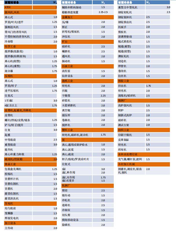
Service coefficient:
1. Select the service factor SFA of the driven equipment from the safety factor table 1
2. Select the service factor SFB of the active device from the safety factor table 2
3. Combine the two safety factors SFA and SFB into a service factor SF
Selection steps 1. Calculate rated torque
1. Choose the appropriate service coefficient
The recommended safety factors are shown in Tables 1 and 2. The safety factor may vary depending on the application, and the main influencing factors include:
1. Types of driving and driven devices
2. Reverse/No Reverse Load
3. Peak torque
The rated torque of the selected coupling specification must be greater than the calculated torque. Verify whether the peak torque of the application is less than the peak torque.
3.Check the drilling capacity of the hub to see if it meets the drilling requirements. If not, choose a larger specification coupling
4.Verify whether the connection method of the shaft/hub can transmit torque. If necessary, the hub can be extended.
Verify whether the rotational speed meets the requirements, and the maximum rotational speed in the sample is the equilibrium rotational speed. If you need a higher speed, please consult Lanling Technology.
Verify whether the dynamic misalignment meets the requirements.
Verify whether DBSE meets the requirements.
Safety factor table1
Safety factor table2

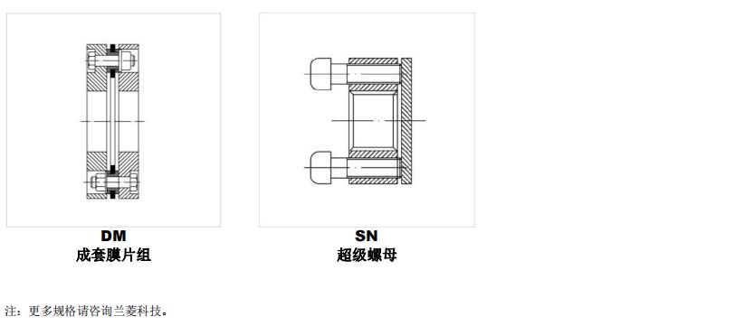
Performance parameters | 6-hole membrane group
Performance parameters | 8-hole membrane group
Performance parameters | 10-hole membrane group
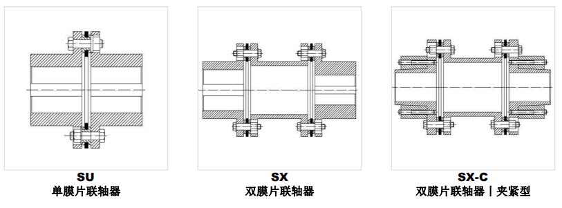
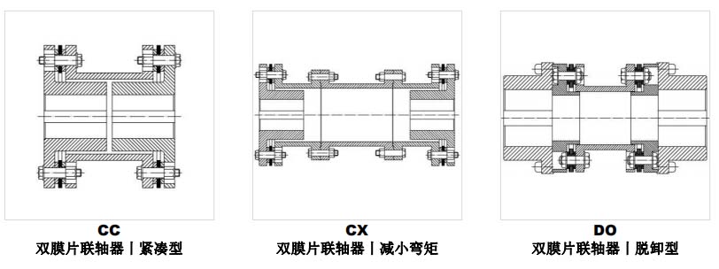
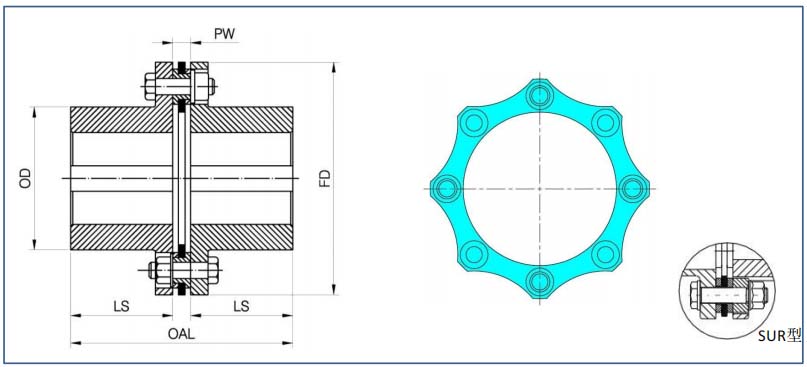
Structural type
Structural dimensions | SU-6 | SUR-6 type
Structural dimensions ح SX-6 ح SXR-6 type
Structural dimensions | CC-6 | CCR-6 type
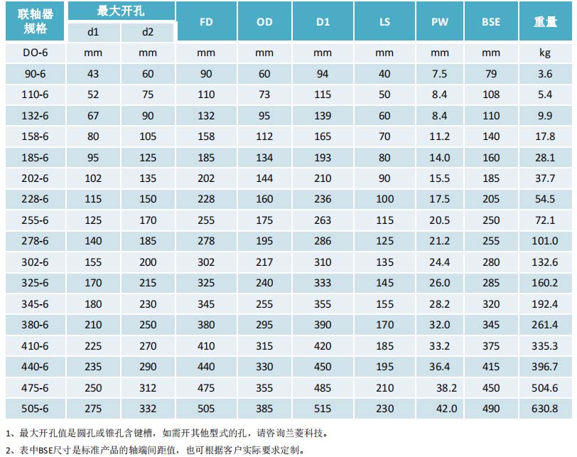
Structural dimensions | DO-6 | DOR-6 type
Structural dimensions | SU-8 | SUR-8 type
Structural dimensions ح SX-8 ح SXR-8 type
Structural dimensions | CC-8 | CCR-8 type
Structural dimensions | DO-8 | DOR-8 type
Structural dimensions | SU-10 | SUR-10 type
Structural dimensions ح SX-10 ح SXR-10 type
Structural dimensions | CC-10 | CCR-10 type
Structural dimensions | DO-10 | DOR-10 type
|
| ��Refresh����Favorites����Print�� ��Close�� |
| Previous��Industrial Chiller��Next��Customization of non-standard environmental test chambers |
- Torque speed sensor
- torque speed sensor
- Magnetic powder clutch
- Magnetic powder brake
- Tension control system
- Deviation control system
- Safety chuck
- Air shaft
- Eddy current brake
- Hysteresis brake
- Hysteresis clutch
- Hysteresis dynamometer
- Eddy current dynamometer
- Electric dynamometer
- Magnetic powder dynamometer
- Hydraulic dynamometer
- Chassis dynamometer
- Drill pipe test bench
- Actuator, worm gear box, test bench
- Engine, axle, gearbox, PTO test bench
- Reducer test bench
- Traction machine test bench
- Motor test bench
- RV, Harmonic and Planetary Test Bench
- Hydraulic pneumatic motor test bench
- Hydraulic wrench test bench
- Testing software
- Slewing bearing test bench
- Acquisition instrument
- New energy vehicle transmission test bench
- Non-standard custom test bench
- High and low temperature test chamber
- coupling
- Industrial chiller